
Modular Spreader Beams
MOD® - The Original and The Best
The MOD® Spreader Beam is the linchpin in Modulift’s product range; a versatile foundation that seamlessly modifies into the CMOD® & TriMOD Spreader Frames and shackle-free TRUNNION Spreader Beam.
Design engineered using 3D Design & FEA Analysis; manufactured to ISO9001, BSEN and DNV quality standards; and available for Same Day Collection or Next Day Delivery. It’s why Modulift is the global market leader below-the-hook.

Choose from MOD® 6 up to MOD® 1100/2000 depending on load and span
Mix and match components to re-use at different spans
Modular, lightweight and portable
Call 01202 621 511 or email [email protected] for a quote. Download the Modulift Brochure to view Load v Span Charts. For worldwide delivery, find your nearest Modulift Distributor.
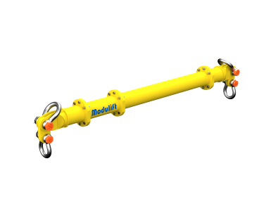
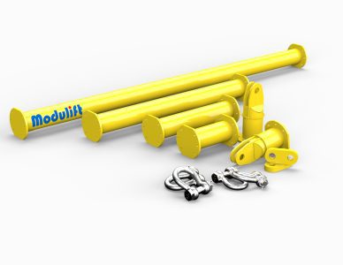
Modular Spreader Beams Sizes
The MOD® Spreader Beams are available in multiple sizes from 6t to 2000t. Find out more about the MOD 6 to MOD 1100/2000 spreader beams below:
Powerful Performers: MOD® Spreader Beams in Action
Modulift’s iconic yellow beams are used across the Construction, Oil & Gas, Breakbulk and Wind sectors to solve lifting problems worldwide. Here are just some of the projects we have worked on. View all Case Studies.

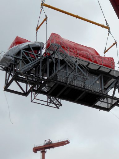

Assembling a Modulift Spreader Beam
Each MOD® Spreader Beam includes your selected struts, two end units, two drop links, and nuts and bolts are supplied as standard. Slings and shackles can be also be purchased at an extra cost. Additional interchangeable struts can be bolted between the end units to either lengthen or shorten, making the beam re-usable at different spans.
Available in different sizes, from the MOD® 6 to the MOD® 1100/2000, all Modulift Spreader Beams are DNV Type Approved up to 2000t capacity. Watch the video to see how a Modulift Spreader Beam should be assembled safely.
Why are MOD® Spreader Beams Globally Recognised?
Don’t worry about long waits and delays. We hold stock of the MOD® 6 to MOD® 600 at our UK warehouse. Available for Same Day Collection or Next Day Delivery. For worldwide delivery, locate your nearest stock-holding Modulift Distributor.
Investing in a Modulift Spreader Beam will continue to pay off for years. You can use your beam again and again, changing the span to suit any project.
With decades of experience under their belts, our in-house team of technical engineers design innovative, high-spec products that help ensure safe lifting around the world.
Our longest strut is only 6m – small enough for the back of a truck! Many of our Spreader Beam components can be handled by one person. Our QJ2 even comes in a handy carrying case complete with shackles.
We can supply storage systems for improved inventory control, organised components, quick retrieval, and mobilisation. These include logistics cradles and stillages.
Strut sizes can be mixed and matched to suit different spans.
We manufacture both standard and custom spreader beams. Need a nonstandard beam? No matter how unconventional the project, our engineers can custom design the ideal beam to suit it.
Our spreader beams are uniquely flexible. From 2 point to 12 point lifts and everything in between, there’s practically no limit to what you can use our beams for. Watch our demonstration video to see how.
Our spreader beams are specially designed to provide you with a lightweight solution so your cranes can work at maximum capacity, reducing the weight of the lifting gear below the hook.
Spreader Beams FAQs
A spreader beam is a lifting device positioned above a load to distribute, or ‘spread’, the weight across two or more lifting points. Unlike a standard lifting beam, a spreader beam is engineered to withstand compressive stress rather than bending stress, which allows it to remain lightweight relative to its lifting capacity.
The beam is designed to keep the sling legs below it at a 90 degree angle, or as close to vertical as the rigging allows, removing horizontal side loading on the load and preventing the item being lifted from being crushed or distorted. When the centre of gravity is central, the weight is shared equally between the two bottom slings, giving a stable, controlled lift.
Spreader beams are used extensively across construction, oil and gas, renewables, breakbulk and general heavy lifting, wherever a wide, fragile or asymmetric load needs to be lifted safely and predictably.
Spreader beams and lifting beams are both classed as below-the-hook lifting devices, but they are engineered to handle loads in different ways and are suited to different lifting scenarios.
A lifting beam sits above the load and is subjected to bending stress along its length, with slings attaching from points along its underside and running down to the load at an angle. A spreader beam, in contrast, is designed to carry compressive stress, holding the sling legs vertical, or near-vertical, to spread the load between two or more attachment points.
Which beam is more suitable for a lift depends on the available headroom, the weight and dimensions of the load, the number of lifting points required and the stability of the item being lifted. As a general rule, lifting beams are chosen when there are bending forces and headroom is restricted, while spreader beams are chosen where the load needs to be kept level, protected from compressive forces, or lifted from a wider span.
The purpose of a spreader beam is to withstand the compressive forces that would be applied to a load from slings, which could damage the load , improving stability, positioning accuracy and safety throughout the lift.
By holding the sling legs vertical, a spreader beam removes the horizontal, or side-loading, forces that would otherwise act on the load, reducing the risk of it being damaged during the lift. This is particularly important for loads that are long, fragile, or irregularly shaped.
In practice, this means spreader beams make lifts more repeatable: rigging teams spend less time rigging , and the risk of load damage is reduced.
The modular design of a spreader beam system allows a single set of components, struts, end units, to be configured into multiple lengths and lifting arrangements, rather than requiring a new bespoke beam for every project.
- Reusability across projects: mixing and matching struts and end units allows one system to perform a wide range of lifts at different spans, rather than sitting idle between jobs.
- Reduced lead times: modular components are held in stock, so project teams are not waiting on the fabrication of a one-off beam.
- Portability: modular spreader beams break down into manageable sections. Modulift’s longest strut is 6m/20’, short enough to transport in the back of a truck, and many components can be handled by one person. The QJ2, for example, is supplied in a carrying case complete with shackles.
- Reduced weight below the hook: modular spreader beams are engineered to be as light as possible for their rated capacity, so cranes can dedicate more of their available capacity to the load itself rather than the lifting gear.
For teams working across multiple sites, this modularity also simplifies inventory and reduces the amount of separate lifting equipment that needs to be purchased, stored and maintained.
There is no single figure that applies to every spreader beam: capacity, more accurately referred to as the beam’s Working Load Limit (WLL), depends on the specific model’s length, width, strut configuration and design specification.
Modulift’s spreader beams range 2t up to 3000t, covering everything from light loads to some of the heaviest modules moved in the oil, gas and renewables sectors. Because capacity can change with span, every spreader beam should be selected using the manufacturer’s load-versus-span chart for the exact configuration being used.
Each Modulift spreader beam design has been proof load tested to twice its rated as part of the design verification process, in addition to third-party DNV Type Approval up to 2000t capacity
In rigging terminology, a ‘spreader beam’ refers to a device or component used to separate or spread apart two or more lifting points or attachment points on a load. Its commonly used in lifting operations to create a stable and balanced lifting configuration, especially when dealing with large or bulky loads that need to be lifted safely.
Spreader beams are classed as lifting accessories and are subject to strict design, manufacturing and in-service regulations, which vary slightly by region.
In the UK and EU, spreader beams must be designed and manufactured to meet BS EN 13155 (Cranes, Safety, Non-fixed load lifting attachments) and BS EN 1993-1-1 (Eurocode 3), and must comply with the EC Machinery Directive 2006/42/EC. In use, they fall under the Lifting Operations and Lifting Equipment Regulations (LOLER) and the Provision and Use of Work Equipment Regulations (PUWER), which require regular thorough examination.
In the US, below-the-hook lifting devices are designed to ASME B30.20 and ASME BTH-1. In Australia, the relevant standard is AS 4991 (Lifting Devices). Internationally, ISO 17096 covers load lifting attachments for cranes, and offshore or marine lifts are frequently designed to DNV Standard for Certification DNV-ST-0378.
Modulift’s spreader beams are DNV Type Approved up to 2000t capacity and are designed in accordance with all of the standards above, with additional third-party verification available for project-specific requirements.
Because a spreader beam is classed as a lifting accessory rather than part of the crane itself, it must be thoroughly examined in its own right, separately from any crane or hoist it is used with. Under LOLER, lifting accessories require a thorough examination at least every 6 months, carried out by a competent person with the practical and theoretical knowledge to identify defects in structural members, welds, attachment points and capacity markings.
A valid crane or hoist certificate does not cover the spreader beam being used with it. Equally, regular use does not reduce the inspection interval: a 6-month examination is required regardless of how frequently the beam is used.
Beyond routine in-service inspection, Modulift spreader beam designs are proof load tested to twice their rated capacity during design verification, and further project-specific load testing or third-party certification can be arranged where a project calls for it.
Modulift spreader beams are manufactured from high-grade structural steel, engineered using 3D design and Finite Element Analysis (FEA) to achieve the best possible strength-to-weight ratio for each capacity in the range. All welding is carried out by coded welders qualified to BS EN ISO 9606-1 , with weld procedures specified and qualified to BS EN ISO 15614-1.
For beams destined for offshore, marine or otherwise corrosive environments, additional protection such as hot-dip galvanising or marine-grade paint systems can be applied to extend service life. Choosing the right steel grade, finish and corrosion protection for the operating environment is an important part of specifying a spreader beam that will perform reliably over its working life, not just at the point of delivery.
Selecting the correct spreader beam starts with the fundamentals of the lift: the weight of the load, the distance between the lifting points (the span), and the number of lifting points required. From there, a number of other factors influence which beam, or spreader frame, is appropriate:
- Headroom: restricted headroom may rule out a cascading beam arrangement in favour of a lower-profile spreader frame.
- Sling angle: slings should be kept as close to vertical as possible to avoid compressive forces on the load; this is one of the core reasons for using a spreader beam in the first place.
- Environment: onshore, offshore and subsea lifts each place different demands on materials, coatings and design verification.
- Load shape and centre of gravity: irregular, top-heavy or off-centre loads may require additional lifting points or a purpose-designed frame.
Because a spreader beam’s capacity reduces as span increases, the correct beam configuration should always be confirmed against the manufacturer’s load-versus-span chart for the exact struts and end units being used, rather than assumed from a single headline capacity. Where a lift falls outside standard configurations, a custom-designed spreader beam or frame can be engineered to suit.
Yes. In the UK and EU, spreader beams, along with lifting beams and lifting frames, are required to carry a physical conformity marking confirming they meet the relevant legislation before they can be placed on the market.
A CE marking demonstrates compliance with the EU Machinery Directive and is required for lifting equipment sold into the EU. A UKCA marking demonstrates compliance with the UK’s Product Safety & Metrology Regulations and is required for equipment sold into the UK. In both cases, the marking should be accompanied by a conformity certificate and should include the manufacturer’s name and address, the CE and/or UKCA mark itself, the series or type designation and serial number (if applicable), and the year of construction.
Buyers and specifiers should check for both the physical marking and the accompanying documentation before putting any spreader beam into service, since the marking alone does not remove the duty to carry out LOLER thorough examinations once the equipment is in use.