News
Custom Lifting Beam Solutions
- Why Standard Beams Are Not Always Enough
- What Custom Lifting Beams Provide
- Custom Lifting Case Studies
- Modulift’s Custom Engineering Capabilities
As equipment, structures and components become larger, heavier, and more complex, lifting across many industries, particularly offshore, renewables and construction, are facing new technical challenges. While standard lifting and spreader beams support a wide range of lifts, many projects now require custom designed solutions engineered for specific loads, environments, and constraints. In this article we explore why standard beams are not always the best option, the typical lifting scenarios that call for custom solutions, and examples of case studies across different sectors.
Why Standard Beams Are Not Always Enough
Off-the-shelf spreader beams are a versatile foundation that can be modified for different spans, working load limits (WLLs) and lifting scenarios. Modular, lightweight and portable, their components can be mixed and matched for different lifting requirements. However, in certain lifting scenarios a custom design will be better suited. For example:
- Irregular or delicate loads – components with unusual shapes, multiple pick points or delicate surfaces, for example wind turbine blades.
- Limited headroom – where taller spreader arrangements are not feasible
- Subsea or harsh environments – requiring alternative materials or corrosion-resistant finishes, for example the custom subsea beam below.
- Multiple centre-of-gravity considerations – equipment where weight distribution shifts during the lift
- Exacting compliance requirements – offshore, aerospace, defence or nuclear sectors where standard documentation is insufficient
- Confined or Restricted Spaces – where the lifting area is tight, such as inside plants, between structures, or beneath decks.
- Lifting Loads with Variable or Adjustable Spans – Projects where the distance between lift points changes, or the same beam must be used for a range of load sizes.
- Rotational or Tilt-Controlled Lifts – When a load must be rotated, tilted, or precisely orientated during the lift, requiring custom lifting points, trunnions, or integrated rotation capability.
In such cases, attempting to adapt a standard beam can introduce risk, additional rigging complexity or compromise operational control. Custom lifting beams allow parameters to be defined such as span, lifting points, weight capacity, centre-of-gravity considerations, and attachment configurations – rather than trying to adapt a generic beam to a challenging load. This ensures safer, more stable lifts, reduces rigging complexity, and avoids ad-hoc workarounds.
What Custom Lifting Beams Provide
A custom lifting beam is engineered specifically around the demands of a defined load, environment and project requirements. Although each design is unique, custom solutions typically allow engineers to specify:
- Span and geometry based on the exact footprint of the load
- Custom lifting points or connection interfaces to match existing lugs or attachment features
- Tailored WLL and structural capacity, supported by relevant calculations and analysis
- Material selection, including high-grade steel or corrosion-resistant options
- Documentation and test requirements such as NDT, proof load testing, or 3.1/3.2 certification
- Weight minimisation where crane capacity or transport constraints apply
Designs often include finite element analysis (FEA) to verify performance under expected load cases, and may incorporate adjustable or modular elements where flexibility is required.
Custom Lifting Case Studies
Modulift has been designing and engineering lifting equipment with high level QA requirements across Breakbulk, Construction, Shipping & Maritime, Oil, Gas & Wind, Cargo, Transport & Logistics and Lifting Gear industries worldwide for over 20 years. Below is a selection of case studies:
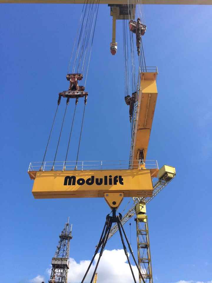
Modulift Provide a Record First Lifting Solution for the Wind Energy Industry and Harland and Wolff
Modulift designed and manufactured a giant lifting rig used for the fast and efficient lifting and assembly of the Repower’s 5MW giant wind turbines at Harland and Wolff in N. Ireland. Responsible for the unloading and assembly of the clean power generators for Vattenfall’s Ormonde Offshore Wind Farm Project in the Irish Sea, Harland and Wolff also had to load them back onto the barges when assembled, for installation in the Irish Sea, creating a need for a rig that could multi-task.
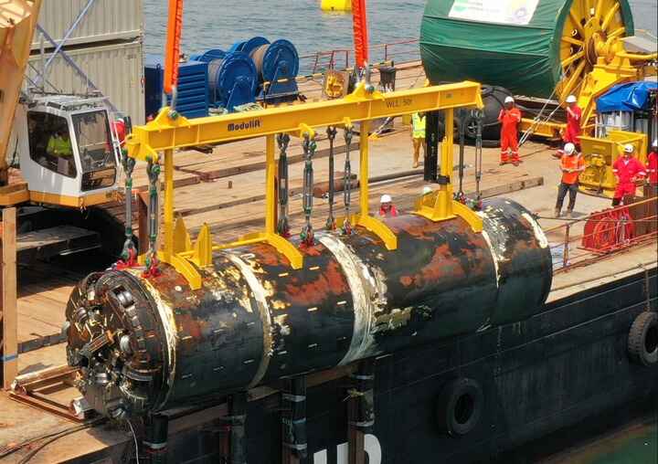
Modulift Custom Subsea Beam Recovers Micro Tunnelling Machine
Modulift designed and manufactured a custom lifting beam that was capable of recovering a micro tunnelling machine from the depths of the sea. In just 8 weeks, the Modulift team designed, produced and delivered a 50t custom beam that was compliant with DNV-ST-N001 standards.
At the request of their customer, a specialist in tunnelling and micro-tunnelling, Modulift delivered a custom solution to meet the stringent DNV industry standards and with a Dynamic Amplification Factor of 2.0.
The beam had to be designed for use above and below the water, taking into account the differences in the centre of gravity location and weight of the micro tunnelling machine due to the buoyancy force. Nevertheless, thanks to the expertise of Modulift’s in-house team, they were able to achieve the correct tilt and balance to ensure a safe and effective lift.
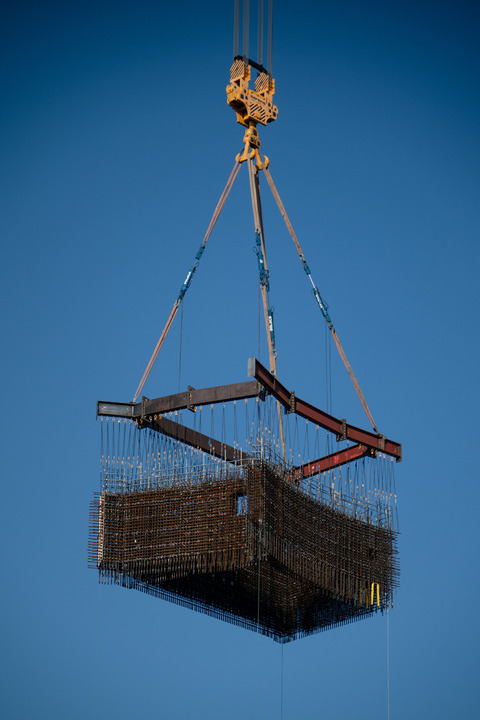
Bylor partners with Modulift to supply custom lifting equipment for Mega Cage installation at Hinkley Point C
Modulift partnered with Bylor at Hinkley Point C to engineer and manufacture a modular 38t custom rebar lifting frame for one of the UK’s most complex infrastructure projects.
A giant prefabricated staircase structure – known as the Mega Cage – was installed into the fuel building of the unit two reactor. The staircase comprises 14 reinforced cages, weighing a combined 170 tonnes.
Modulift’s custom modular lifting frame, measuring 19m x 13m with a WLL of 205t, was specifically engineered so that each lifting point aligned precisely with vertical slings, resulting in an unusual but highly efficient configuration. Measuring 19m x 13m with a WLL of 205t, the modular frame was assembled directly on site, cutting unnecessary transport costs while guaranteeing precise load handling. The streamlined installation accelerated the build, enabling concrete pouring to begin sooner.
Modulift’s Custom Engineering Capabilities
Modulift works closely with clients from concept to completion, to design and manufacture custom lifting equipment for extreme weights, unusual geometries, and demanding environments. Whether it’s a lifting arrangement for a high-rise building project, a subsea beam for offshore deployment, or a precision-engineered beam for aerospace components, Modulift delivers certified, fully traceable solutions.
To discuss your next custom design project, contact the Modulift projects team today on 01202 621 511 or email [email protected]